
Solar can supply a share of a telecom site’s daily energy while the existing AC equipment remains responsible for poor-weather support and battery recovery. The retrofit works when the new PV converter and the existing plant follow compatible voltage, current and control rules.
The first design conversation should establish the operating sequence. During a sunny period, how much of the DC load should PV carry? When a cloud reduces output, which source responds? If AC disappears, which controls continue operating? Those questions determine the integration work before the panel quantity is finalised.
Draw each conversion path to the same load
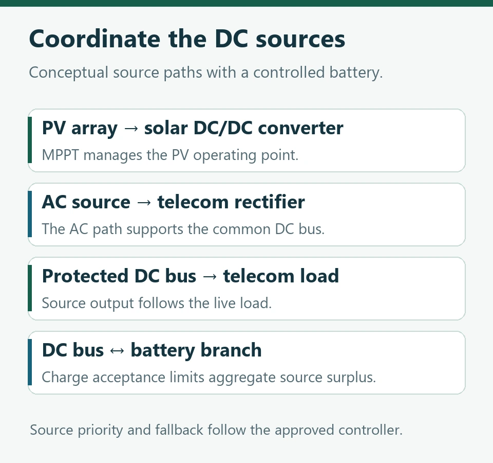
A DC-coupled arrangement can send the PV array through an appropriate DC/DC converter with maximum power point tracking, then into the protected telecom DC system. The AC rectifier follows a separate path from utility or generator supply to the bus. The battery absorbs permitted surplus or supplies a deficit according to its availability and control limits.
A rectifier system for telecom includes the AC conversion path and its relationship with the controller, battery and distribution. Huijue Group’s guide helps identify those components when deciding which existing functions a solar retrofit can retain.
Some projects use an AC-coupled arrangement instead. Trace its PV inverter, transfer arrangement and AC-to-DC stage explicitly. Its behaviour during a utility outage depends on the specified grid-forming or backup capabilities and the actual circuit arrangement.
Solar priority needs a defined control method
The site may prioritise PV by adjusting permitted rectifier output, using compatible source setpoints or invoking a supported energy-management mode. Select a method documented for the actual equipment and battery. The control design should state which device can change output and what happens when communications are interrupted.
For example, independently setting two chargers to different voltages can change which source supplies current. It can also affect battery charging and the load voltage. The final settings need to fit the approved electrical windows and the platform’s control method.
ITU-T L.1211 addresses smart control of photovoltaic systems installed at base stations. Its scope makes the interaction between energy sources a relevant part of telecom solar design. The project specification must translate that into operating states for the offered equipment. ITU-T L.1211
Combine the charging contributions
Consider an explicitly hypothetical 54 V DC bus. The live load is 80 A. At the selected moment, PV contributes 70 A and the rectifier contributes 40 A. Ignoring dynamic effects and with all readings taken at the same boundary, the surplus is 30 A.
If the battery’s permitted charge current at that moment is 20 A, the sources need to reduce their combined contribution by 10 A, equivalent to about 540 W at the example voltage. The reduction should follow the approved source-priority rule. This calculation reveals a control requirement even though each source could individually remain within its own rating.
The same ledger should include cases with little PV and depleted storage. Solar availability varies across the day, while the AC source may return for a limited interval. Size the retained recovery path against those combined conditions.
Test the transitions that matter to the site
A useful commissioning plan moves from stable operation into a small number of defined events. Cover falling PV output, AC loss and return, a battery charge restriction and a control-communications interruption. Specify the load, battery condition and acceptance measurements for each event before the test.
Record bus voltage, load current, source currents and battery current on the same time base. The result should explain how the site continued supplying its critical load and how each control limit was respected. Electrical testing belongs under the project’s approved method and qualified personnel.
A solar offer becomes easier to compare once it contains this operating sequence alongside the equipment list. The buyer can identify which PV hardware is new, which AC functions remain in service and who is responsible for the combined controls and handover tests.
Huijue Group works on telecom energy equipment and integration. This article presents general engineering guidance and explicitly labelled planning examples.